Bridge Gate vs Sludge Ladle: Which Is Better For Dead Space in Molding?
During the mold manufacturing process, the design and selection of the product window position have a crucial impact on the final product’s quality and production efficiency. As a senior engineer, I hope to explore the use of “Bridge Gate” and “Sludge Ladle” methods in mold manufacturing to determine which is more suitable for the product hallow position – dead space. This article will discuss the pros and cons of bridging and non-bridging approaches to form an effective analytical solution.
Bridge Gate Technology in Mold Manufacturing
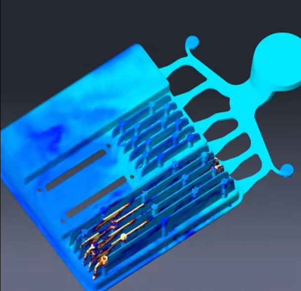
Bridging technology involves using connecting pieces to link adjacent slag bodies, ensuring that the clamp head is located inside the slag body, thereby providing limitation and support to resist pressure. This technology mainly ensures the stability of the mold under stress.
Design
The design of bridging connections requires considering the support function of the clamp head, connecting rod, and positioning post ends inside to ensure that the slag body does not disengage under pressure.
Pros and Cons of Bridge Gate
Advantages:
- Prevent Backflow: Bridging can effectively block the backflow caused by the metal liquid flow, ensuring smoother metal flow.
- Change Filling Sequence: By altering the filling sequence, the end position of the fill can be changed, making the metal flow smoother.
Disadvantages:
- Potential Impact on Product Quality: If the bridging design is improper, it may lead to poor metal flow, thus affecting the final product’s quality.
Applications
In mold manufacturing, the application of Bridge Gate design, gating bridging structure manufacturing technology, anti-deformation mold bridging, as well as PCB window processing and plastic molding improvement schemes can significantly enhance mold reliability and stability.
- Gating Bridging Structure: Using bridging inserts can solve the problem of low reliability and stability caused by the direct crossover of gating and core-pulling channels. For instance, in an automotive part mold, bridging inserts were used to prevent deformation when the gating system and core-pulling mechanism intersected, significantly reducing the defect rate.
- Anti-Deformation Mold Bridging: Includes parts such as fixed bridges, shear plates, etc., working together to prevent mold deformation during forming. In a recent project involving a large appliance, the anti-deformation bridging ensured the mold retained its shape despite high injection pressures.
- PCB Window Processing: Creating small holes or notches on the PCB board to facilitate welding or other functional needs. For example, in a consumer electronics mold, PCB window processing allowed for precise placement of components, improving assembly efficiency.
Example:
In a complex die-casting mold design project, the designer needed to handle a complex structure with multiple runners and gates. To ensure stability during the machining process, the designer employed bridging technology. Specifically, the designer built temporary bridging connections between the various runners and gates, which were removed during the final assembly.
Through this method, the designer was able to effectively handle complex structural issues in the mold, ensuring stability during the machining process, thereby improving machining precision and efficiency.
Sludge Ladle Technology in Mold Manufacturing
Sludge Ladles are primarily used in the die-casting process to contain the initial cold metal liquid entering the cavity and the gases and oxides mixed in, thereby improving the quality of the finished product. Sludge Ladle is manufactured through welding, offering high strength and durability.
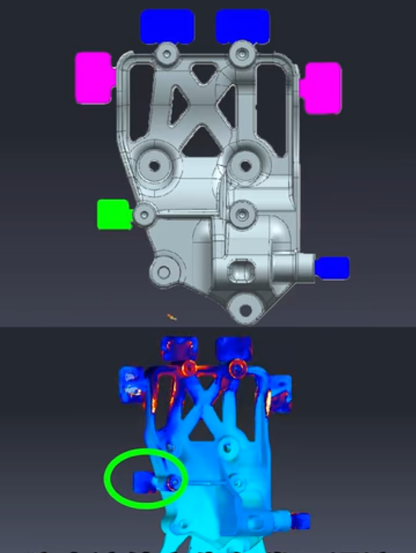
Pros and Cons
Advantages:
- Contain Cold Metal and Gases: Prevents local vortices.
- Exhaust Function: Avoids casting defects like gas shrinkage.
- Supplement Metal Liquid Pressure: Ensures product consistency and completeness.
Disadvantages:
- Complex Design: Improper design may lead to poor results.
- High Pressure: Slag ladles under high pressure may deform or get damaged.
Applications
In mold manufacturing, the Sludge Ladle design is mainly used to handle product window positions, ensuring the quality and consistency of castings.
- Optimized Gating and Sludge Ladle Design: Solves the manual optimization process of gating and Sludge Ladle through simulation analysis, saving modification time. For instance, in an industrial machinery part mold, optimized slag pocket design eliminated flow defects and reduced cycle time.
- Control Metal Flow State: Prevents local vortices, improving the overall quality of castings. In a recent aerospace component project, controlling the metal flow with Sludge Ladle ensured the structural integrity of the casting.
- Modular Design: Allows flexible adjustment of sludge ladle design based on different product needs. A mold for a medical device utilized modular Sludge Ladle to accommodate various sizes and shapes of components.
- Parametric Design: Combines model design and finite element analysis, improving design efficiency and accuracy. In an automotive engine part mold, parametric design of slag ladle reduced development time and improved performance.
- Thermal Fatigue Analysis and Optimization: Uses numerical simulation and fatigue life prediction software to optimize structural design, extending sludge ladle lifespan. For example, a mold for heavy machinery parts underwent thermal fatigue analysis, resulting in a design that withstood high temperatures and prolonged use.
Application of Sludge Ladle Technology
Slag ladle technology is primarily used to address clearance issues in mold design. Clearance refers to the gap between parts, such as the gap between the ejector pin and the template. In plastic mold design, clearance standards typically include the unilateral clearance of components such as positioning rings, nozzle hangers, support pillars, and ejector blocks.
Example:
In a specific plastic mold design project, the designer needed to ensure a 0.1mm unilateral clearance between the positioning ring and the panel, and a 0.5mm unilateral clearance between the nozzle hanger and the panel. This was to ensure that the injection nozzle of the machine could quickly align with the mold’s sprue bushing, thereby shortening the mold setup time and reducing errors.
By using slag technology, designers can employ a modular design approach, combined with finite element analysis and parametric design, to quickly and selectively add the required part attributes. For example, a parametric design system for welded slag ladles developed on the SolidWorks software platform not only meets the diverse and personalized needs of customers but also improves design efficiency.
In Mold Manufacturing, Which is More Suitable for Product Window Positions: Bridging or Sludge Ladle?
In mold manufacturing, choosing between slag ladle or bridging technology to handle the window position depends on specific product requirements and mold structure:
- Product Shape and Complexity: For complex shapes requiring frequent core-pulling, bridging technology is recommended for increased reliability and stability. In a recent mold for complex automotive components, bridging technology provided the necessary support and reduced defect rates.
- Production Efficiency and Cost: For simpler die-cast parts, slag ladle technology is preferable due to its simplicity and lower cost. For example, in a consumer electronics mold, slag pockets were used to maintain cost efficiency while ensuring product quality.
- Simulation Analysis: Optimizing the gating and slag ladle design through simulation analysis improves casting quality. In a recent industrial equipment project, simulation-driven slag pocket design reduced trial-and-error adjustments, improving overall production efficiency.
Both slag ladle and bridging technologies have unique advantages and application scenarios. In mold manufacturing, the most suitable technology should be selected based on specific design requirements and production conditions to achieve the best manufacturing results and product quality.

