Engineering (Technical) Drawing View Types, Pros, Cons, Differences and Instructions
Engineering drawings specify various information about the parts to be manufactured. To show the part properly, there are different types of views and prospective used on the drawing. Here we’ll introduce different types of views in technical drawings with their features, advantages, disadvantages, drawing methods, and differences between them.
Types of Views in Engineering (Technical) Drawings
1. Perspective View
Perspective view in engineering drawing simulates how the human eye perceives objects, providing a highly realistic representation. It effectively conveys spatial depth and the three-dimensional nature of objects by using one or more vanishing points where parallel lines appear to converge. This view also incorporates foreshortening, where objects appear smaller as they recede into the distance, creating a more natural and dynamic appearance.
How to Make
- Determine the Type of Perspective: Start by deciding whether you need a one-point, two-point, or three-point perspective based on the object’s orientation and complexity. One-point perspective is ideal for objects viewed straight on, with all lines converging at a single vanishing point. Two-point perspective is suitable for objects viewed at an angle, with lines converging at two vanishing points. Three-point perspective adds a third vanishing point for vertical lines, creating a more complex and dynamic view.
- Set Up Reference Planes: Establish the ground plane (GP), a horizontal reference plane on which the object rests; the picture plane (PP), the vertical plane where the perspective view is formed; the horizon line (HL), the line where the ground plane and horizon plane intersect; and the station point (SP), the observer’s eye position relative to the object.
- Draw the Object’s Top and Front Views: Begin by sketching the top view of the object on the picture plane, followed by the front view directly below the top view.
- Establish the Vanishing Points: For one-point perspective, place a single vanishing point on the horizon line. For two-point perspective, position two vanishing points on the horizon line. For a three-point perspective, add a third vanishing point either above or below the horizon line.
- Draw Visual Rays: Connect the corners of the top view to the station point, creating visual rays that intersect the picture plane. These intersection points are referred to as piercing points.
- Construct the Perspective View: Use the piercing points and vanishing points to draw the perspective view, ensuring that lines converge at the appropriate vanishing points to maintain the sense of depth.
- Refine and Detail: Add necessary details and refine the drawing to ensure clarity and accuracy. Utilize guidelines and construction lines to maintain proper proportions and alignment.
Advantages
- Provides a more artistic and visually appealing representation of objects.
- Even non-technical individuals can easily understand the drawing due to its realistic appearance.
- Useful in fields like architecture and design, where the visual impact and spatial understanding are crucial.
Limitations
- More complex to create compared to orthographic or isometric views.
- Can introduce distortion in measurements and angles, making it less suitable for precise technical drawings.
- Typically only shows three sides of an object, which may not be sufficient for detailed technical analysis.
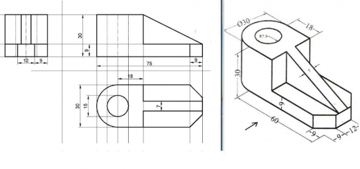
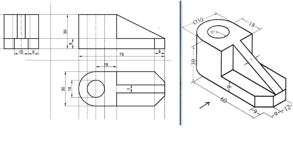
2. Orthographic View
Orthographic view is a fundamental technique used in technical drawing and engineering design to represent three-dimensional objects in two dimensions. It involves projecting the object onto multiple planes (typically front, top, side, bottom, and back views) that are perpendicular to the line of sight. Each view shows the object from a different angle, providing a comprehensive understanding of its geometry. The key principles include perpendicular projection, true size and shape representation, standard views, hidden lines, and center lines.
How to Make
- Understand the Object: Thoroughly understand the object you intend to draw, identifying its main features, dimensions, and specific details.
- Choose Views: Determine the essential views needed to represent the object accurately, such as front, top, side, and isometric if necessary.
- Set Up the Drawing Space: Prepare a clean and appropriately scaled drawing space to ensure detailed representation without overcrowding.
- Draw the Primary Views: Begin by drawing the primary views (front, top, and side views) using light construction lines to establish the basic structure before finalizing with darker lines.
- Maintain Consistency: Ensure consistency in scale, line thickness, and projection methods across different views for a cohesive and accurate orthographic projection.
- Label Features: Clearly label the features of the object in each view, using annotations to identify dimensions, angles, and critical details.
- Add Hidden Lines: Include dashed or dotted lines to represent hidden or obscured features of the object to convey the complete structure.
- Create Isometric Views (Optional): Add isometric views if necessary to provide a more three-dimensional understanding.
- Check for Consistency: Regularly check for consistency between the different views to ensure dimensions align correctly and there are no discrepancies.
Advantages
- Provides precise and accurate representations of three-dimensional objects.
- Follows standardized conventions, ensuring clear communication and collaboration among professionals across different disciplines and industries.
- Allows for the creation of multiview drawings, enabling designers and engineers to visualize the object’s form and spatial relationships from different angles.
- Facilitates dimensional analysis and tolerancing, essential for quality control and manufacturing processes.
- Integrates seamlessly with Computer-Aided Design (CAD) software.
Limitations
- Limited visualization of 3D objects, as it lacks the ability to convey depth perception and spatial relationships effectively.
- Creating orthographic drawings can be time-consuming and labor-intensive, especially for objects with intricate geometries or numerous components.
- Requires specialized knowledge and skills in technical drawing, geometry, and drafting techniques, necessitating extensive training for proficiency.
3. Isometric View in Engineering Drawing
Isometric view is a type of 3D representation of an object or a scene in which all three dimensions (length, width, and height) are depicted. In an isometric drawing, the three axes form a 120-degree angle with one another, resulting in an enduring perception of depth without altering the scale of the objects represented. Unlike perspective drawings, where lines converge at a vanishing point, isometric illustrations retain parallelism between the axes. This projection method utilizes the isometric scale, where all three axes are equally measured at a consistent ratio. Thus, one can easily represent an object’s height, width, and depth in a coherent manner. Whether depicting mechanical components or architectural designs, the isometric view simplifies complex structures, making it an invaluable tool for engineers.
How to Make
- Understand the Object: Thoroughly understand the object you intend to draw, identifying its main features, dimensions, and specific details.
- Set Up the Drawing Space: Prepare a clean and appropriately scaled drawing space. Using an isometric grid can save time and effort.
- Draw the Primary Axes: Begin by drawing the three primary axes at 120-degree angles to each other. Typically, the vertical axis is drawn vertically, and the other two axes are drawn at 30 degrees to the horizontal.
- Sketch the Object: Using the primary axes as a guide, sketch the object’s features. Ensure that lines parallel to the axes are drawn at the correct angles.
- Add Details: Include all necessary details such as dimensions, annotations, and hidden lines if required.
- Refine the Drawing: Clean up the sketch, ensuring that all lines are straight and dimensions are accurate.
- Review: Check the drawing for consistency and clarity to ensure it accurately represents the object.
Advantages
- Provides a realistic and clear representation of three-dimensional objects on a two-dimensional plane.
- Enhances visualization and communication of ideas, especially for non-technical individuals.
- Facilitates efficient problem-solving in designing and engineering by depicting multiple aspects simultaneously.
- Useful for technical documentation, manufacturing, and assembly instructions.
- Integrates seamlessly with modern technologies like Computer-Aided Design (CAD), 3D Printing, and Virtual Reality (VR).
Limitations
- It may not be suitable for objects with complex curved surfaces or non-rectangular geometries.
- It can create a distorted appearance due to the lack of foreshortening.
- Typically only provides a single view, which may not be sufficient for detailed technical analysis.
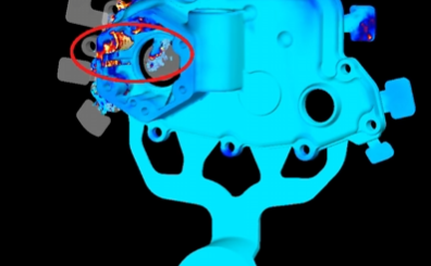
4. Section View
A section view is a representation created by imagining an object being cut open with a cutting plane. The part of the object between the observer and the cutting plane is removed, and the remaining portion is projected onto a projection plane.
How to Make
- Choose the Cutting Plane: The cutting plane is an imaginary plane that slices through the object. Its placement depends on the features you want to highlight. Consider symmetry, complexity, and clarity.
- Draw the Cutting Plane Line: The cutting plane line indicates the location and direction of the cut. It consists of thick dashed lines, arrows indicating the direction of viewing, and labels identifying the section view (e.g., Section A-A).
- Project the Section View: Imagine looking at the object from the direction indicated by the arrows on the cutting plane line. Project the visible edges and surfaces onto a new view.
- Add Section Lines: Section lines (also called cross-hatching) are thin, parallel lines that indicate the cut surfaces. They are typically drawn at a 45-degree angle and spaced evenly. Different materials are often represented by specific section line patterns.
- Include Necessary Details: Add hidden lines, center lines, dimensions, and annotations to ensure clarity. Hidden lines are typically omitted unless necessary for understanding.
Advantages
- Provides a clear view of internal or hidden features of an object, eliminating the need for guesswork and assumptions.
- Enhances visualization and communication of complex internal geometries, improving understanding among engineers, machinists, and designers.
- Improves manufacturing accuracy by providing detailed information for machining, fabrication, and assembly.
- Standardizes technical drawings, following ISO, ANSI, and BIS standards for universal interpretation.
- Reduces errors in interpretation caused by overlapping hidden lines in regular views.
Limitations
- Complexity: Creating section views can be time-consuming and requires a good understanding of the object’s geometry.
- Standard Dependency: Section views rely on adherence to specific drawing standards, which can be challenging for beginners.
- Potential for Misinterpretation: If not properly annotated, section views might still lead to misunderstandings, especially for non-technical audiences.
5. Cut-out View
A cut-out view is similar to a section view but differs in that it only cuts a smaller portion of the model. This view helps in reducing the number of orthographic views in the drawing, thus simplifying the overall representation.
How to Make
- Identify the Area of Interest: Determine the specific area of the object that needs to be revealed.
- Draw the Break Line: Use a thin continuous line to indicate the boundary of the cut-out area. This line should be drawn freehand to clearly delineate the sectioned portion.
- Remove the Specified Portion: Imagine removing the portion of the object in front of the break line to reveal the internal features.
- Project the Internal Features: Draw the visible internal features within the cut-out area, ensuring they are accurately represented.
- Add Annotations and Dimensions: Include necessary annotations and dimensions within the cut-out view to provide clarity and precision.
- Review for Consistency: Ensure the cut-out view aligns with other views on the drawing and accurately represents the object’s internal details.
Advantages
- Reduces the number of different views on a single drawing, making the drawing less cluttered and easier to read.
- Emphasizes specific features of interest without the need for additional views.
- Improves clarity by removing unnecessary parts of the object, allowing for a better understanding of the internal structure.
- Reduces the complexity of the drawing, making it easier for non-technical individuals to interpret.
Limitations
- Complexity: Creating a cut-out view can be complex for objects with intricate internal geometries.
- Standard Dependency: Requires adherence to specific drawing standards for proper interpretation.
- Potential for Misinterpretation: Without clear annotations, the cut-out view might be misinterpreted, especially by those unfamiliar with engineering drawings.
6. Detailed View
A detailed view is a scaled-up version of a specific section of an orthographic view. It is particularly useful for complex models with small intricacies that are difficult to clearly represent in the main views.
How to Make
- Identify the Area of Interest: Determine the specific area of the object that requires detailed representation.
- Draw the Reference Line: Enclose the area of interest within a circle or freehand line to indicate the location of the detailed view.
- Label the Detailed View: Mark the detailed view with a capital letter and label it as “DETAIL” for clear identification.
- Scale the View: Choose an appropriate scale to enlarge the detailed view, ensuring that all features are clearly visible.
- Add Dimensions and Annotations: Include necessary dimensions, annotations, and notes within the detailed view to provide clarity and precision.
- Review for Consistency: Ensure the detailed view aligns with other views on the drawing and accurately represents the object’s features.
Advantages
- Enhances clarity by providing a clear and detailed representation of intricate features that may not be visible in the main views.
- Reduces the need for multiple views by focusing on specific areas, making the drawing less cluttered.
- Improves communication and understanding among engineers, machinists, and designers by providing precise details.
- Facilitates manufacturing and assembly by providing exact dimensions and specifications for complex components.
Limitations
- Limited Scope: A detailed view focuses on a specific area, which may not provide a comprehensive understanding of the entire object.
- Complexity: Creating detailed views can be time-consuming and requires a good understanding of the object’s geometry and the drawing standards.
- Potential for Misinterpretation: Without clear labeling and annotations, detailed views might be misinterpreted, especially by those unfamiliar with engineering drawings.
7. Auxiliary View
An auxiliary view is a special type of orthographic projection used to show the true shape and size of a surface that is not parallel to any of the primary projection planes (front, top, or side views). It is particularly useful for objects with inclined or oblique surfaces that appear distorted in standard orthographic views.
How to Make
- Identify the Inclined Surface: Determine the specific inclined surface that needs to be shown in true size and shape.
- Establish the Auxiliary Plane: Imagine a plane parallel to the inclined surface. This plane will be used to project the view.
- Draw the Reference Line: In the principal view where the inclined surface is best visible, draw a reference line parallel to the edge of the inclined surface.
- Project Perpendicular Lines: From the principal view, project lines perpendicular to the reference line. These lines carry the dimensional information to the auxiliary view.
- Construct the Auxiliary View: Using the projected lines as a guide, construct the auxiliary view, ensuring the true shape and size of the inclined surface are accurately represented.
- Label the View: Clearly label the auxiliary view to avoid confusion. Typically, this involves using a descriptive term like “Auxiliary View A-A” with corresponding arrows indicating the direction of sight.
Advantages
- Provides a clear and accurate representation of inclined or oblique surfaces, improving understanding and communication.
- Facilitates precise measurement and dimensioning of complex geometries.
- Reduces the need for multiple views by focusing on specific features, making the drawing less cluttered.
- Enhances visualization for manufacturing, assembly, and inspection processes.
Limitations
- Complexity: Creating auxiliary views can be time-consuming and requires a good understanding of the object’s geometry and projection principles.
- Standard Dependency: Requires adherence to specific drawing standards for proper interpretation.
- Potential for Misinterpretation: Without clear labeling and annotations, auxiliary views might be misinterpreted, especially by those unfamiliar with engineering drawings.
8. Exploded View
An exploded view is a technical drawing style that shows the individual parts or the assembly order of an object as a diagram. It provides a clear and intuitive way to communicate complex assembly processes, helping viewers understand the spatial relationships between components, how they fit together, and the sequence of assembly or disassembly steps. The components are separated but arranged to show their relationship and assembly sequence. This view is often used in technical documentation, assembly instructions, and maintenance manuals. It can also be used in marketing and advertising to showcase a product’s features and technology.
How to Make
- Identify the Components: Determine the individual parts or components that need to be shown in the exploded view.
- Arrange the Components: Separate the components and arrange them in a way that shows their relationship and assembly order. This can be done manually or using CAD software.
- Use CAD Software: Many CAD programs like SOLIDWORKS and NX offer tools to create exploded views. You can select and drag components to create explode steps, adjust their positions, and add trails or lines to indicate their original positions.
- Add Annotations and Labels: Include written notes, dimensions, or symbols to clarify components, materials, and measurements.
- Review and Refine: Check the exploded view for clarity and accuracy, ensuring it effectively communicates the assembly process.
Advantages
- Provides a clear and intuitive way to communicate complex assembly processes.
- Simplifies the visualization of complex structures, reducing the overwhelming nature of intricate designs.
- Enhances design clarity by revealing the quantity of components required and the materials used.
- Facilitates effective communication between team members, clients, and stakeholders.
- Aids in identifying parts for maintenance, repair, or replacement.
- Useful for technical documentation, assembly instructions, and maintenance manuals.
- It can be used in marketing and advertising to showcase a product’s features and technology.
Limitations
- Creating exploded views can be time-consuming and requires a good understanding of the object’s geometry and assembly process.
- It may not be necessary for simple assemblies where the order of assembly is already clear.
- Can be resource-intensive, especially when creating detailed 3D exploded views.
Engineering Drawing Views Comparison
| View Type | 2D/3D | Number of Faces Displayed | Projection Direction | True Size | Visual Effect | Measurement Accuracy | Depth Representation |
|---|---|---|---|---|---|---|---|
| Perspective View | Realistic 3D | Multiple faces | Converges at vanishing points | No | Realistic, depth emphasized | Low | Yes |
| Isometric View | 3D | Three faces | Parallel at 120° angles | Yes (along axes) | Clear 3D effect | Medium | Yes |
| Section View | 2D | One face (cross-section) and others | Perpendicular to cutting plane | Yes | Clear internal details | High | No |
| Cut-out View | 2D | One face (cut-out area) and others | Perpendicular to break line | Yes | Clear specific area | High | No |
| Detailed View | 2D | One face (detailed area) | Zoomed in on specific area | Yes | High detail clarity | High | No |
| Auxiliary View | 2D | One face (inclined surface) | Perpendicular to inclined surface | Yes | True shape of inclined surfaces | High | No |
| Exploded View | 3D | Multiple faces of components | Components separated | No | Assembly relationship shown | Low | Yes |
| Orthographic View | 2D | Multiple faces (front, top, side) | Perpendicular to projection plane | Yes | Precise and accurate | High | No |
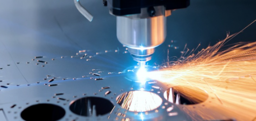
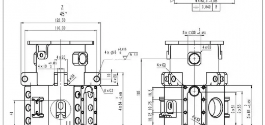
Which View Is Essential in CNC Part Drawing?
In technical drawings for CNC machining parts, the Orthographic View is the most essential type of representation. This view illustrates a three-dimensional object in two dimensions by utilizing multiple perspectives, typically including the front, top, and side views. One of its primary advantages is that it provides accurate dimensions and clear relationships between features, which aids machinists in visualizing the part’s geometry. To create an Orthographic View, begin by selecting the most informative perspective as the front view, then project the other views, such as the top and right side, from this initial view. Ensuring proper alignment and adding dimensions for clarity are crucial steps in this process.
While Orthographic Views are vital for conveying precise dimensions and shapes, other view types like Isometric and Sectional Views also play significant roles in specific contexts. The Isometric View offers a three-dimensional perspective of a part, helping to understand its shape and depth, particularly in complex geometries or assembly configurations. On the other hand, Sectional Views cut through a part to reveal internal features, making them especially useful for parts with internal cavities or holes that require precise machining. Each type of view contributes uniquely to the overall understanding of the part being designed and manufactured.