CNC Tool Length Compensation: Principle, G-Code & H-Code, Offset Identification & Methods
In CNC machining, tool length offset can occur due to wear and tear, replacement, or other factors. If not compensated for, the original tool path will not be executed accurately, affecting the machining precision and quality. By using length compensation commands (such as G43 H), the position of the cutting tool can be adjusted to ensure precise machining.
Principle of CNC Tool Length Compensation
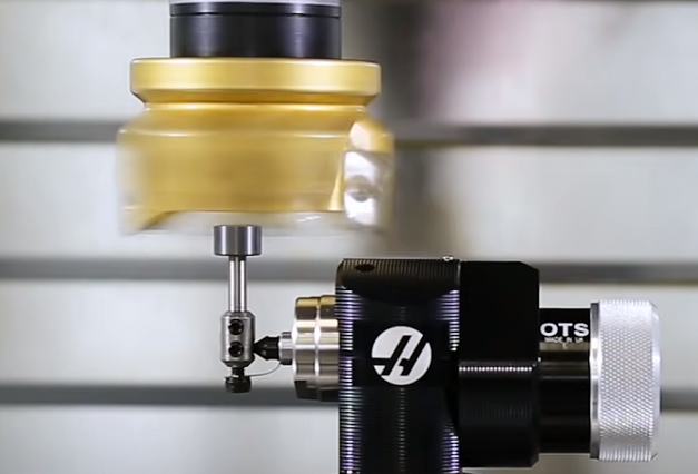
The tool length compensation works by using the G-code and H-code to adjust the tool’s position on the Z-axis. When the actual tool length differs from the programmed theoretical length, the tool’s movement along the axis needs to be adjusted to ensure machining precision. Specifically, the G43 or G44 and H codes are used to implement tool length compensation. G43 means Tool Length Compensation + (plus) and G44 means Tool Length Compensation – (minus).
How to Identify Tool Length Offset?
1. Check the simulation results and actual workpiece to ensure they match. If the edges are not properly processed, or the thickness is not accurately controlled, it may indicate a need for length compensation.
2. Check if the tool shape affects the ideal cutting path. If the tool has a significant elastic deformation or cannot form a precise cutting edge, length compensation may be necessary.
3. Verify if the control system and CAM software provide length compensation functionality. If available, set up the relevant parameters.
4. Measure the actual tool nose radius and compare it to the programmed value. If there are differences, adjust the compensation.
5. Test different workpiece materials or types to see if the error values vary. Obtain correction parameters through separate testing.
6. After long-term cutting, check if the tool has worn out and deformed. If severely worn, re-measure the parameters.
7. When machining new workpieces or materials, perform a trial run to ensure the actual results match the planned ones.
8. When producing batches of the same product, slight differences may exist between batches. Old parameters may not be applicable.
9. After system upgrades or machine modifications, previous parameters may need to be revised.
Operation and Instruction Differences on Different CNC Machines
Length compensation is widely applied to various types of CNC machines, including milling machines and lathes. Although different CNC machine brands have different operation procedures and command formats for length compensation, the principle remains the same.
1) Command format:
The general format for tool length compensation commands is G43 or G44, followed by the Z-axis end value and the tool length offset storage address (H). For example: G43 Z H or G44 Z H. The H represents the tool length compensation offset number, ranging from H00 to H99.
Example of tool length compensation with G43 code (3-aix milling machine):
; Define tool length compensation parameter
N10 LLENGTH=-2; Tool tip length compensation, assumed 2mm in advance
; Start milling first surface
N20 G00 X100 Y100 Z100 ;Rapid move to start point
N30 G01 Z80 F1000; Move Z axis down to cutting depth
N40 G01 X50 Y150 F500 ;Start milling first surface
; Execute length compensation correction
N50 G43.1 H1; Call tool length compensation, H address represents path 1
N60 G01 X0; Execute motion after correction
; Finish first surface cutting
N70 G00 Z100; Z axis moves up away
; Start milling the second surface
N80 G00 X100 Y100 Z100
N90 G00 Z80
N100 G01 X50 Y50 F500 ;Start milling second surface
; The second process also executes correction
N110 G43.1 H1
N120 G01 X0
; Finish the entire milling program
N130 G00 Z100
N140 G00 X200 Y200
N150 M30 ;End program
2) Operation procedure:
In the FANUC system, the specific operation steps for tool length compensation may differ from other systems. Refer to the machine and CNC system operation manuals or relevant documents to ensure correct and safe operation.
3) Storage and application:
Once the tool length compensation value is set, it will not be lost even if the machine is powered off, allowing programmers to program according to the standard tool length without knowing the actual tool length. Each tool corresponds to a unique tool compensation number, which is retained even after the machine is powered off, making it convenient for future use.
4) Others:
Different CNC systems may have different parameter specification methods. For example, in screw thread commands, FANUC and Mitsubishi machines have different parameter specification methods. In actual operation, regularly inspect and maintain the tool and machine to ensure machining precision and stability.
How to Adjust Tool Length Compensation Parameters for Different CNC Systems?
– Using G-code: In CNC programming, G41, G42, G43, and G44 commands involve tool length compensation. These commands need to be used in Z-axis movement and must be guided by Z-axis movement commands. By specifying the tool length compensation number (such as H01-H99), the corresponding tool length compensation value can be called.
– Manual pre-setting: This method involves manually calculating the tool compensation value and inputting it into the CNC system for programming. This method is suitable for situations where the tool length variation is small.
– Automatic tool compensation: Some CNC systems have automatic tool compensation functionality, which can be called through programming to perform tool length compensation. This method does not require manual input of compensation values, and the system will automatically compensate according to the preset parameters.
– Using a tool presetter: It is recommended to use a tool presetter to measure the actual tool length and input the value into the tool length compensation register. This method ensures the accuracy of tool length compensation.
– System parameter setting: In the CNC system’s parameter setting interface, find the tool length compensation-related parameter setting options. Move the cursor to the area to be set or modified, input the value, and press the input key to confirm and complete the tool length compensation parameter adjustment.
Factors Affecting the Effectiveness of CNC Tool Length Compensation
– Tool wear: Tool wear during use can lead to differences between the actual and original lengths. Tool length compensation commands can be used to correct these differences, ensuring machining precision.
– Tool replacement or installation errors: If the tool is replaced or installed incorrectly, it can also lead to differences between the actual and expected lengths. Tool length compensation commands can be used to adjust these differences, avoiding re-programming and re-alignment.
– Operator skills and experience: The operator’s skills and experience also affect the effectiveness of tool length compensation. Skilled operators can more accurately perform tool length compensation, improving machining precision.
– Tool shape and trajectory issues: Changes in the tool shape and machining trajectory can also affect the effectiveness of tool length compensation. Reasonable compensation methods can be used to solve these problems, ensuring machining precision.
– Tool extension length: If the tool extension length is too short, it can lead to frequent adjustments to the tool length, affecting machining efficiency. Therefore, it is necessary to reasonably control the tool extension length to balance precision and efficiency.
To ensure the effectiveness of tool length compensation, take the following measures:
- Regularly detect and record tool wear, and dynamically adjust the compensation parameters.
- Re-measure the tool dimensions after replacement, and update the compensation values.
- Improve the operator’s tool management and length compensation operation skills.
- Develop specialized length compensation plans for different materials and workpiece shapes.
- Consider the tool nose radius and other factors affecting the machining trajectory, and correct the path accordingly.
- Reasonably control the tool extension length to avoid frequent adjustments.
- Perform simulation validation and fine-tune the compensation parameters for critical processes.
- Ensure smooth data transmission, and avoid incorrect operation leading to parameter leakage.
- Periodically evaluate the compensation method, and refine or optimize the measures.
- Strengthen operator training and assessment management, and improve their skills and experience.

