Contour Milling vs Plunge Milling, Which One to Choose | Clearance Angle Guide for Machining
Proper clearance design improves efficiency and accuracy. Factors like materials, part geometry, and surface requirements determine clearance size. Contour milling is suitable for small clearances while plunge milling quickly removes large amounts of material from deep cavities. Linear projection applies coordinate transformations to machine curves on cylinders.
What Is a Clearance Angle in CNC Machining?
In CNC machining, a clearance angle refers to the withdrawal angle of each cutting path in the multi-pass machining process, in order to ensure that the cutter maintains a certain gap between the entry cutting position and the exit cutting position, avoiding empty cutting or collision. This design prevents parts from interfering with each other during assembly and improves machining efficiency and accuracy. In the machining process, the design of clearance angles can significantly improve machining efficiency and accuracy. By implementing clearance planning, chips can be smoothly discharged, preventing blockages and reducing high temperature and friction caused by chip accumulation, thereby extending tool life and maintaining machining precision. Additionally, selecting appropriate tool diameters and offset tool paths can also help reduce issues in the machining process, such as avoiding the formation of pits on the edge during face-cutting.
Specifically, clearance angles are typically used in the following situations:
– Mold design: During mold design, it is necessary to consider the positional relationship between parts to ensure that they do not interfere with each other during the assembly process. For example, leaving a certain gap between the pin and the mold base is a clearance processing method.
– Electrode processing: In electrode processing, if it is not possible to provide clearance on the product merging surface, clearance can be provided on the outer merging surface to prevent the electrode from being over-penetrated and the merging surface from running out of aluminum. Additionally, the merging surface should have at least 2mm of clearance.
– Jewelry and die design: When designing jewelry, it is also necessary to consider clearance issues. For example, leaving a clearance of 2mm on one side of the jewelry not only facilitates CNC machining but also facilitates fitting the mold.
– Face milling: For high model cores, providing a clearance of approximately 0.5mm on one side is sufficient in the design. This avoids the need to design a slope, especially when machining high-model cores, this clearance can be processed using face milling for 15-30 minutes.
What Are the Design Standards for Clearance Angles in CNC Machining?
Slope top slide clearance: For slope top slides, the side needs to have a specific clearance position to ensure normal operation. For example, the selection of the hanging plate height H and width T dimensions should meet specific standards.
R corner or C corner clearance: In plastic mold design, all non-sealing R positions need to have clearance processing to ensure smooth processing. Additionally, oblique guide blocks often use C corners with rounded corners to avoid the B board, making it easier to process with CNC.
Methods for processing clearance holes:
Clearance holes can be processed using line cutting or machine center drilling. For example, a 0.2mm diameter tungsten wire can be used for right-angle clearance, or a center drill and milling cutter can be used for processing on a slanted surface. For larger lower mold PL sealing positions, a 0.15mm clearance standard can be adopted.
Parameter settings for clearance surfaces:
When programming, step distance, feed, and speed should be appropriately increased to improve machining efficiency. The parameter settings for clearance surfaces should be greater than the required negative 0.015mm to ensure machining precision.
How to Determine the Size of Clearance Angles in CNC Machining?
Each material has its unique properties, which significantly impact the machining process and the functionality and durability of the final product. For example, high-hardness materials such as stainless steel and titanium have high strength but are difficult to machine, which can easily lead to tool wear. Therefore, when selecting materials, it is necessary to consider these factors.
Selecting suitable materials based on specific application requirements is crucial. For example, aluminum and copper are relatively soft materials and are easy to machine, while titanium and stainless steel require more precise machining techniques. Additionally, material consistency is also very important to ensure the uniform quality of parts. During the design phase, efforts should be made to optimize the size and shape of parts to reduce the waste of raw materials and lower production costs. For example, selecting standardized blank sizes can effectively reduce waste.
The degree of tool wear, ease of machining, and surface quality requirements differ between materials. These machining characteristics directly impact the selection of CNC machining parameters and tool selection. For example, softer materials may require more careful machining to avoid size changes. The different properties of materials also affect the level of CNC machining accuracy that can be achieved. Softer materials are more prone to deformation, and their machining accuracy needs to be more strictly controlled.
In the CNC machining process, evaluating and optimizing the design of clearance angles to improve machining accuracy is a complex and multi-faceted task. The following are some key steps and methods:
– When designing convex and concave model faces, measures such as offsetting concave rounded corners or reducing clearance can be taken. These measures can be realized through CNC programs to ensure the precise clearance of convex and concave model faces.
– Using high-quality raw materials and tools is the key to achieving high-precision machining. Poor-quality materials and tools will affect the precision and smoothness of the machining process.
– Ensure that the machine tool and tool are in good working condition, and maintain and calibrate the equipment regularly to reduce machining errors caused by equipment failure.
– For large products, the wall clearance of the divided face is helpful in reducing the cost of machining. By optimizing the design of the divided face, machining errors and waste can be effectively reduced during the machining process.
– During the production process, if there are errors, first find out the main factors affecting machining errors, and then take measures to eliminate or reduce these factors. For example, when machining parts with shaped faces, the main measure is to reduce the error of the shaped tool.
– In the rough machining phase, quickly remove most of the machining surplus, and then gradually process each surface one by one. This way, not only can the production efficiency be improved, but the precision and surface roughness of the parts can also be guaranteed.
How to Machine Clearance Angles, Contour Milling, or Plunge Milling?
Contour milling:
– Applications: Contour milling is applicable for roughing and finishing operations of a large amount of cutting materials and steep wall precision machining, such as a cavity, convex platform, and corner machining.
– Characteristics: Contour milling is a cutting method where the tool sequentially cuts the material, and the object can include parts with curved surfaces.
– Advantages: Contour milling is suitable for situations where materials need to be gradually removed. Especially in the design of single-sided clearance of approximately 0.5mm, this processing method can effectively reduce the need for secondary processing.
Plunge milling:
– Applications: Plunge milling is especially suitable for quickly cutting a large amount of metal materials for parts, such as deep and steep-walled cavity parts or difficult-to-process vertical side walls.
– Characteristics: This method uses the continuous up and down motion of the tool to quickly and largely remove materials, especially when machining deep vertical side walls.
– Advantages: Plunge milling reduces the deformation of parts, improves machining efficiency, and is particularly efficient for curved surface machining, groove machining, and tool protrusion length that is greater than the processing depth.
Based on the size of the clearance angle, choose the milling process:
Small clearance angle (less than 2mm): If the clearance angle is small, it is recommended to use contour milling. This is because contour milling can perform layer-by-layer cutting in a small clearance area, avoiding the sliding knife phenomenon caused by a small clearance area. Additionally, for a small clearance area, contour milling can more precisely control the cutting depth and path, ensuring the quality of processing.
Large clearance angle (greater than 2mm): For larger clearance angles, especially when a large amount of material needs to be quickly removed, plunge milling is more suitable. Plunge milling can efficiently perform large-area rough machining, and can also process complex curved surfaces and grooves. Additionally, in the case of large clearance angles, plunge milling can significantly improve machining efficiency and reduce the deformation of parts.
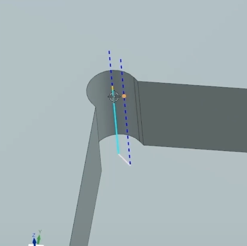
How to apply linear projection in plunge milling?
– Use the projection angle to define the working surface. The projection angle is determined by two angles (usually the angle between the Z-axis and the Y/Z plane).
– When writing macro programs, it is necessary to modify appropriately according to the principle of coordinate transformation between lines and rotating coordinates. This can achieve the processing of common curves such as circles, ellipses, and hyperbolas on cylindrical curved surfaces.
– Using advanced CNC programming software such as PowerMill, linear projection four-axis linkage can be realized, without drawing driving surfaces, simplifying the path creation process. Additionally, VERICUT’s background check function can be used to save machining time and ensure processing quality.
– The angle of inclination of the line to the working surface and its impact are key. When the line is parallel to the working surface, the projection is the real length; when the line is perpendicular to the working surface, the projection is concentrated at one point; when the line is inclined to the working surface, the projection is less than the real length.
– In practical operations, ensure that the projection image moves accurately to improve the quality and precision of processing. At the same time, pay attention to monitoring the test results, so as to timely adjust and optimize the processing parameters.