Differences Between Profile vs Runout for GD&T Applications
In this blog post, we’ll explore the differences between the profile symbol and runout symbol for controlling round cylindrical shafts. This content is drawn from Unit 13 of our GeoTol Pro online program, which is linked in the description below.
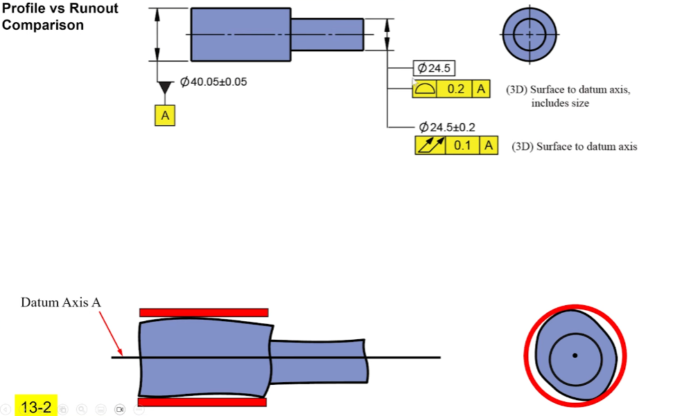
Let’s dive into a simplified example of two shafts. We have the larger diameter selected as datum feature A with a size tolerance, and the other diameter needs to be kept coaxial (centered). The two options we have now are profile or runout.
Key Differences: Profile vs Runout
Profile Tolerance
Profile requires a basic dimension for the size, creating a tolerance zone that wraps around the true profile of the surface. For instance, with a basic diameter of 24.5, the tolerance zone would be 0.1 in and 0.1 out, forming two coaxial cylinders centered around the datum axis.
- Controls: Size and coaxiality.
- Fixed Size: The tolerance zone is centered around the basic diameter.
Profile tolerance ensures that any variation in the feature’s size and how centered it is will be controlled within the tolerance zone. If the feature is off-center or too far out of the specified size, it will fail the profile tolerance.
Runout Tolerance
Runout, on the other hand, is a surface control that does not include the size. The tolerance zones for runout are variable in size, meaning they do not need to be centered around a fixed basic size.
- Controls: Coaxiality, location, orientation, and form.
- Variable Size: The size of the cylinders is not fixed.
Runout tolerance ensures that the feature runs true, but the size can vary. Therefore, a large or small shaft can still have perfect runout as long as it runs true.
Practical Example: Rotating Shaft
Consider a rotating shaft that mounts into a main bearing fixed in the housing with a sensor above it. There is a necessary air gap or clearance between these parts to ensure proper functioning.
First, we select the datum feature. The shaft that mounts into the bearing will be our datum feature A, creating our datum axis. We want to keep this centered to maintain the necessary clearance between parts.
Profile Tolerance
Profile tolerance includes the size with its profile tolerance, controlling both size and location in one go. For example, if we have a basic diameter of 56 with a profile tolerance of 0.2, it effectively means 56 ± 0.1 per side.
Runout Tolerance
If we use runout, we have to give a separate size tolerance (e.g., 56 ± 0.2) and then apply the runout tolerance. This requires splitting the tolerance allowance between size and runout (e.g., 56 ± 0.1 for size and 0.1 for runout).
Manufacturers generally prefer profile tolerance because it provides more flexibility. It allows for a larger size tolerance range while maintaining good coaxiality, which is easier to achieve in manufacturing processes like lathe operations.
When to Use Runout
Runout is ideal when the size of the feature is less critical, but how true it runs is more important. Examples include pulleys and seals, where the size can vary as long as the part runs true.
Example: Brake Drum
Consider a brake drum on a large truck. The drum must stay centered and run true to ensure proper functioning of the brake shoes. Here, size is less critical because the shoes are adjustable. Thus, runout is a suitable control:
- Datum Features: The inside face and a pilot diameter are selected.
- Runout Tolerance: Applied to ensure the drum runs true relative to the datum axis.
Total runout is preferred over circular runout for ensuring the entire surface runs true, preventing tapering and ensuring even wear on the brake shoes.
Understanding the differences between profile and runout tolerances is crucial for selecting the right control method for your application. Profile tolerance combines size and coaxiality control, offering flexibility in manufacturing. Runout tolerance is ideal for applications where true running is more important than size.