How To Prepare Technical Drawings for CNC Machining Precision Parts?
Creating accurate technical drawings is fundamental for successful CNC machining. These drawings serve as the communication bridge between designers and machinists, ensuring the final product matches the intended specifications. This article provides comprehensive guidance on preparing technical drawings that meet CNC machining requirements, covering essential elements from dimensioning standards to material specifications.
Essential Components of CNC Technical Drawings
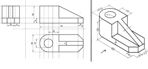
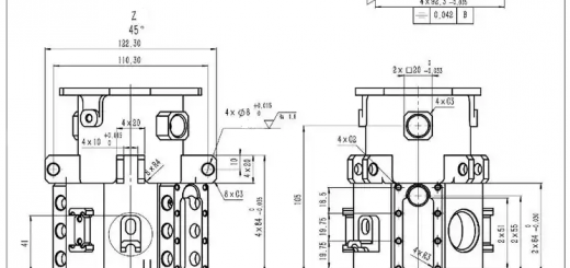
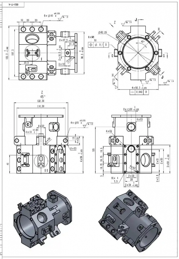
Every CNC machining drawing must include several critical components to ensure manufacturability. The title block contains vital information such as part name, drawing number, revision history, material specification, and scale. Orthographic projections (typically front, top, and side views) provide complete representation of the part geometry. Isometric views can supplement these for complex parts.
Dimensioning must follow industry standards (ISO or ASME) with all critical dimensions clearly marked. Include both overall dimensions and detailed feature dimensions. For CNC machining, position dimensions should reference a single datum rather than using chain dimensioning to prevent tolerance stacking.
Tolerances should be specified based on functional requirements. General tolerances can be noted in the title block, while critical features require individual tolerance callouts. Standard machining tolerances typically range from ±0.1mm to ±0.025mm for precision parts.
Surface finish requirements must be indicated where necessary, specifying roughness values (Ra) and any special finishing processes. Common CNC surface finishes range from 3.2μm Ra for standard machining to 0.4μm Ra for fine finishing.
Geometric Dimensioning and Tolerancing (GD&T) should be used when part functionality depends on precise form, orientation, or location of features. This standardized system ensures proper interpretation of design intent.
When preparing drawings for CNC machining, always consider the manufacturing process limitations. Avoid over-dimensioning—only specify critical dimensions and tolerances that affect part functionality. Unnecessarily tight tolerances significantly increase machining costs.
Material Specifications and Machining Considerations
The technical drawing must clearly specify the material to be used, including grade or alloy designation when applicable. Common CNC materials include:
| Material Type | Examples | Machining Characteristics |
|---|---|---|
| Aluminum Alloys | 6061, 7075 | Excellent machinability, good strength-to-weight ratio |
| Stainless Steel | 303, 304, 316 | More challenging to machine, requires appropriate tooling |
| Titanium | Grade 2, Grade 5 | Difficult to machine, requires slow speeds and rigid setup |
| Plastics | Delrin, Nylon, PTFE | Easily machined but requires careful handling to avoid deformation |
Material selection significantly impacts machining parameters and costs. When specifying materials, consider the part’s functional requirements rather than defaulting to high-performance materials that may be unnecessarily expensive.
For optimal CNC machining results, the drawing should consider manufacturing constraints such as minimum feature size, maximum depth-to-width ratios for pockets, and practical corner radii. Typical guidelines include:
- Minimum hole diameter: 1mm for most materials
- Minimum wall thickness: 0.5mm for metals, 1mm for plastics
- Standard corner radii: 0.5mm or 1/3 of cavity depth
- Maximum thread length: 3 times the hole diameter
Drawing Standards and File Formats
Adherence to recognized drafting standards (ISO 128 or ASME Y14.5) ensures clear interpretation of technical drawings. Standard practices include:
Line Weights: Use varying line weights to distinguish between object lines (thick), hidden lines (medium), and center lines (thin). This visual hierarchy improves drawing readability.
View Layout: Arrange orthographic views according to first-angle or third-angle projection, clearly indicating which standard is used in the title block.
Annotation: Place notes and dimensions outside the part outline when possible, using leaders to point to features. Avoid crossing dimension lines.
Section Views: Use section views to reveal internal features, properly labeling cutting planes and maintaining consistent hatch patterns.
For CNC machining, traditional 2D drawings are often supplemented with 3D CAD models. Common file formats include:
| Format | Usage | Advantages |
|---|---|---|
| DWG/DXF | 2D drawings | Industry standard for technical drawings |
| STEP | 3D models | Neutral format, maintains parametric data |
| IGES | 3D models | Legacy format, widely compatible |
| Parasolid | 3D models | High precision, used in advanced CAD systems |
Special Requirements and Advanced Features
Certain part features require special attention in CNC machining drawings:
Threads: Specify thread type (metric, UNC, UNF), size, class of fit, and length. For critical applications, include thread runout requirements. Internal threads smaller than M2 or #0 may require special tooling.
Chamfers and Fillets: Clearly dimension chamfer angles and sizes. For fillets, specify whether they’re mandatory for strength or simply for deburring. Standard fillets of 0.5mm can often be assumed unless specified otherwise.
Critical Features: Highlight features that require special machining processes such as grinding, honing, or EDM. Include any necessary inspection requirements like CMM verification or surface roughness testing.
For complex parts, consider including a machining sequence note or separate setup drawings if certain features must be machined in a specific order to maintain dimensional stability.
Heat Treatment and Post-Processing: If the part requires heat treatment (annealing, hardening), plating (nickel, chrome), or other surface treatments (anodizing, powder coating), these should be clearly specified with applicable standards and coverage requirements.
Quality Assurance and Inspection Criteria
The technical drawing should define inspection requirements and quality acceptance criteria. This includes:
Critical Dimensions: Identify dimensions that require verification with specific inspection methods (micrometer, CMM, optical comparator).
Material Certifications: Specify if material certifications (mill test reports) are required and which properties need verification.
Surface Integrity: Note any restrictions on surface defects like tool marks, burrs, or microcracks that could affect performance.
Functional Testing: Include any assembly tests or functional requirements that the finished part must meet.
Properly prepared CNC machining drawings serve as both manufacturing instructions and quality control documents. They should contain sufficient information for production without being overly prescriptive about non-critical features. Regular collaboration between design and manufacturing teams helps optimize drawings for both functionality and manufacturability.