Introduction to Fixed Axis & Simultaneous Axis CNC Machining
CNC machining, renowned for its precision and repeatability, relies heavily on the interplay of fundamental concepts. Among these, “fixed axis” and “simultaneous axis” stand out as cornerstones of controlled tool movement, enabling the creation of intricate designs on workpieces. This article delves into the essence of these concepts, highlighting their significance and how they work in unison to drive CNC machining processes.
What is Fixed Axis and Simultaneous in CNC Machining?
- Fixed axis machining refers to the mode where, in equipment like five-axis CNC milling machines, only three linear axes (such as X, Y, Z) move synchronously, while the other two rotational axes (such as A, B, C) engage only when necessary to change the machining range. This mode reduces the number of synchronous axes, making path generation easier, ensuring stable cutting tool forces, minimizing operational errors, and enhancing high-speed cutting and surface machining quality.
- Simultaneous involves the system coordinating multiple coordinate axes’ movements according to a specific pattern. For example, in CNC engraving machine systems, if the system can control movements along the X, Y, and Z axes, it’s termed a three-axis control system. If it can control movements along X, Y, Z, A, B, and C axes, it’s called a six-axis control system. More axes under simultaneous indicate a more powerful CNC device capable of handling more complex part structures.
In summary, fixed axis machining primarily focuses on reducing the number of synchronous axes to improve machining precision and efficiency, while simultaneous control emphasizes coordinating multiple axes to accomplish more complex machining tasks. Both have distinct applications and advantages in CNC machining.
What Are Specific Applications of Fixed Axis & Simultaneous Axis in CNC Machining
Fixed Axis Machining Applications:
– High-Speed Cutting: Path generation is easier in fixed axis machining mode due to fewer synchronous axes, ensuring stable cutting forces and benefiting high-speed cutting.
– High Surface Quality Requirements: Minimal operational errors lead to better surface machining quality. Traditional path planning methods like parallel scanning are more effective under fixed axis machining mode.
– Fully Enclosed Freeform Surface Model Machining: Fixed axis machining is suitable for addressing clamping planning issues in fully enclosed freeform surface model machining.
– 3+2 Axis Machining: Also known as 3+2 axis machining, it involves controlling feed axes (X, Y, Z) and adjusting tool direction or worktable position on the machine to achieve optimal cutting conditions for part machining.
Simultaneous Axis Applications:
– High-Precision Complex Part Machining: 5-axis simultaneous machines facilitate easy measurement of the center position of rotating axes, reducing adjustment time and enabling high-precision five-axis simultaneous control machining. These machines can include configurations like dual rotary tables, dual tilting heads, or a combination of both.
– Multi-Axis Complex Path Programming: 5-axis simultaneous allows simultaneous control of multiple axes (e.g., three linear axes and two rotational axes). Such programming is highly complex and typically created using CAM systems.
– Precision Deep Hole Drilling: Specific CNC machining units such as deep hole drilling units are ideal for precision machining of deep holes and complex-shaped parts.
– Multi-Functional High-Performance CNC Machine Models: Suitable for various machine tools, these models can meet the machining requirements of complex parts.
Comparison Study of Fixed Axis Machining and Simultaneous Axis Machining in Enhancing Machining Precision and Efficiency
Machining Precision
Five-axis Simultaneous Machining:
– Five-axis simultaneous machining achieves precise cutting and assembly of workpieces through coordinated movements of five axes (X, Y, Z, M, S). This method is renowned for its high precision and finds wide applications in aerospace, automotive manufacturing, electronics, and electrical industries.
– In specific applications, such as machining aircraft impellers, five-axis simultaneous machining significantly enhances machining precision and mitigates errors accumulated from multiple clamping operations.
For example, the positioning accuracy of the BA S03 type five-axis simultaneous machining center can reach +/- 5 arc seconds, ensuring positioning accuracy throughout the machining area meets the Tp0.01mm standard specified by VDI DGQ 3441.
Fixed Axis Machining:
– Under fixed axis machining mode, tool orientation relative to the workpiece is achieved through the coordinated movements of rotational and linear axes of a five-axis CNC machine, without the need for re-clamping. This approach is suitable for parts requiring high precision and relatively simple structures.
– While fixed axis machining can achieve certain levels of precision, its flexibility and capability to adapt to complex surfaces are generally not as robust as those of five-axis simultaneous machining.
Machining Efficiency
Five-axis Simultaneous Machining:
– Five-axis simultaneous machining equipment allows completing all machining operations in a single setup, significantly reducing process complexity and time consumption.
– For instance, in batch production scenarios, optimizing NC programs through simulation allows more accurate calculation of cycle times and early-stage development and optimization of NC programs, thereby enhancing overall machining efficiency.
– Five-axis simultaneous machining also reduces non-machining time, further enhancing production efficiency.
Fixed Axis Machining:
– Due to its relatively simpler structure, fixed axis machining is typically used for small parts that do not require highly complex surface treatments or in specific applications with lower process requirements.
– Although fixed axis machining can effectively control production costs in certain scenarios, its lower flexibility may limit its efficiency in handling complex parts and surfaces compared to five-axis simultaneous control machining.
– So 5-axis simultaneous machining has shown more outstanding performance in improving machining accuracy and efficiency. It can not only complete multi-directional and multi angle machining of complex parts with one clamping, but also achieve the optimal cutting angle through five-axis simultaneous, thereby improving machining quality and efficiency. In contrast, although fixed axis machining can achieve high accuracy and efficiency in certain specific applications, its flexibility and ability to adapt to complex surfaces are not as strong as 5-axis simultaneous machining.
How to Select the Suitable CNC Machining Mode (Fixed Axis or Simultaneous) Based on Different Materials and Part Structures?
3-Axis Machining:
Suitable for uniform convex surfaces or relatively simple geometric shapes, typically utilizing three controlled axes (X, Y, Z) for machining.
For example, for simple geometries like planes or cubes that do not require complex rotations or tilting operations, three-axis machining mode is suitable.
5-Axis Fixed Machining:
Applicable to complex parts that require defining a unique tool axis vector direction, such as deep cavities or surfaces with continuous curvature changes.
In this mode, the tool may undergo continuous or intermittent 5-axis movements relative to the workpiece, while maintaining a consistent tool axis vector direction.
For instance, for parts with complex surfaces or requiring high-precision directional machining, 5-axis fixed machining mode is suitable.
5-Axis Simultaneous Machining:
Used for parts requiring simultaneous control of multiple axes to achieve complex shape machining, such as complex molds and parts.
Five-axis simultaneous machining allows the tool to rotate at any angle during machining, enabling more efficient material removal and higher surface quality.
For example, for parts with intricate internal cavities or complex external contours, five-axis simultaneous machining offers greater flexibility and precision.
Special Mode Selection:
In some cases, combining different modes can optimize machining results. For instance, using three-axis machining for rapid material removal during roughing stages and switching to five-axis simultaneous machining for improved surface quality and dimensional accuracy during finishing stages.
Additionally, depending on specific machining requirements, different feed modes and cutting strategies such as equal feed mode or zigzag cutting mode can be selected to ensure optimal cutting performance.
How to Achieve Efficient Simultaneous Control in CNC Numerical Control Systems for Complex Parts?
– Multi-axis Simultaneous Technology: Multi-axis simultaneous forms the foundation for machining complex parts. For instance, five-axis simultaneous control technology is utilized in machining multi-axis parts such as aircraft engine impellers, turbine blades, and molds. This technology provides high stability and capability for complex surface machining, ensuring high precision requirements are met.
– High-speed High-precision Control: To handle complexity during high-speed cutting, CNC control systems must possess rapid data processing capabilities and advanced functionalities. This includes using 32-bit or 64-bit CPUs, multi-processor architectures, and features like feed-forward control and large number lookahead segment processing. Additionally, technologies such as NURBS interpolation, jerk acceleration, and smooth interpolation can enhance interpolation accuracy during high-speed operations.
– Intelligent Servo Control: Intelligent servo control optimizes machine tool conditions in real-time (e.g., load and temperature), achieving high-speed, high-precision, and high-quality machining results. This technology maximizes spindle utilization and reduces cycle times. For instance, technologies like FANUC’s HRV+ control technology avoid frequency-variable mechanical resonance, achieving accuracy of 1μm roundness and 2μm/div.
– Efficient Feed and Spindle Control: Adaptive feed axis acceleration/deceleration adjusts according to different workpieces and materials, enhancing machining efficiency and precision. HRV spindle control achieves high-response and high-precision spindle control, optimizing deceleration corresponding to inertia and shortening cycle times through high-speed current control and optimal direction function.
– Real-time Correlation and Synchronization Functions: Real-time correlation calculates axis position offsets for multi-axis simultaneous motion, while synchronization allows switching between multiple-process systems and provides various synchronization modes such as high-precision control and initial high-precision control.
– Advanced Programming and Macro Program Expansion: Expansion of user macro program functions and enhanced computation performance with added array variables and SWITCH-CASE branch syntax enhance usability. These features flexibly adapt to various mechanical structures, support independent operation of multiple programs, and coordinate actions between programs.
What Are the Main Challenges and Solutions Faced by Fixed-Axis and Simultaneous Technologies In Practical Applications?
Main Challenges:
1. High Precision Requirements:
- Five-axis simultaneous CNC machine technology involves significant complexity, requiring simultaneous control of multiple axes to achieve machining of complex surfaces.
- When drawing ellipses with four-axis simultaneous control, variations in the U-axis angular velocity can lead to jitter and stepping issues, affecting machining quality.
2. Complex Mechanical System Tuning:
- Servo gain adjustment and the coordination of PLC trigonometric curve profiles pose challenges in servo solution development. Particularly on high-speed rotating Z-axis, setting gains too high can cause vibrations during motor start and stop.
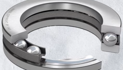
3. Accurate Coupling Alignment:
- Couplings need to compensate for manufacturing and assembly errors; otherwise, equipment operation noise, vibration, and spindle/bearing wear or damage can occur.
- Misalignment of couplings can lead to unstable rotor system motion, causing equipment vibration and bearing wear issues.
4. Dynamic Balancing Issues:
- As industrial technology advances, the shaft systems of rotating machinery become increasingly complex and compactly laid out, limiting the application of holographic dynamic balancing methods.
5. Material and Environmental Factors:
- Variations in temperature, materials, and working conditions require computer modeling and simulation testing to identify weak points and torque tolerances.
Solutions:
1. Optimized Design and Calibration:
- Enhance control precision in multi-axis simultaneous systems through algorithm improvements and additional sensors. For instance, optimizing arc fitting algorithms can reduce jitter and stepping phenomena in four-axis simultaneous systems.
- Reduce vibration in servo systems by adjusting speed gains and using high-precision feedback devices.
2. Advanced Coupling Designs:
- Select appropriate coupling types based on workload and installation conditions. Use fixed rigid couplings for stable workloads where strict alignment between two shafts is necessary. Adjustable rigid couplings are suitable for applications with significant manufacturing and assembly errors.
- Employ automatic balancing technology to address shutdown issues caused by imbalance in large rotor systems.
3. Dynamic Balancing Technology Application:
- Implement a three-dimensional integrated dynamic balancing system combined with automatic balancing technology to minimize downtime losses caused by rotor imbalance.
4. Computer-Aided Design and Simulation:
- Utilize computer modeling and simulation techniques to test performance under various operating conditions, optimizing design solutions. Finite element method (FEM) is used to identify weak points and torque tolerances in rotating couplings.
5. Innovative Bolt Connection Technology:
- Develop new bolt connection technologies such as the Expander system to enhance coupling reliability and adaptability.