Stamping Die Sheet Metal Spring Back Formula & Calculation Chart for Blending Process
During the bending process of stamping dies, material spring back is a significant technical issue that designers inevitably encounter and must manage by devising compensation strategies or reducing its impact. Calculating springback involves multiple factors including the properties of the material, die design, and specific conditions during the stamping process. Formulas and adjustment methods for spring back are designed to help engineers predict and control shape changes in stamped parts after unloading, ensuring the geometric accuracy of products. Understanding the factors influencing spring back is crucial for enhancing product quality and precision. This article provides a detailed exploration of the subject.
1. What is Springback in Stamping Die?
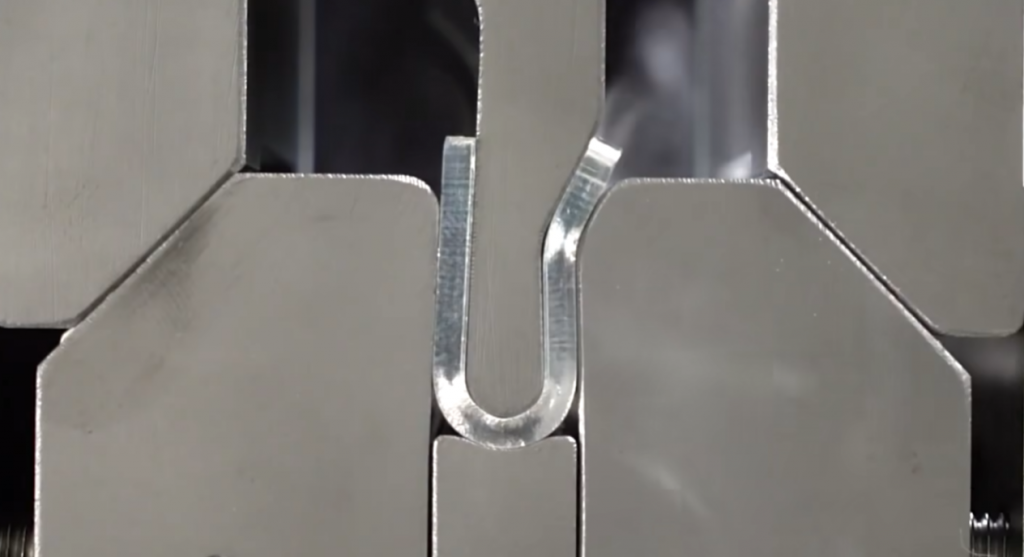
Springback occurs because metal materials always exhibit elastic deformation during plastic bending. Thus, when the bending moment is removed, the bending radius of the bent part becomes inconsistent with the die dimensions. Springback is typically expressed in terms of angular springback (∆a) and curvature springback (∆q).
2. Main Factors Affecting Sheet Metal Spring Back in Stamping Die
- Material Properties:
Different materials (such as steel, aluminum, and stainless steel) have varied elastic moduli and yield strengths, directly influencing the degree of springback. The size of the springback angle is proportional to the yield point (S) and inversely proportional to the elastic modulus (E). Harder materials have greater elastic recovery capability, leading to larger springback. Material thickness also affects stress distribution and influences springback.
- Bending Angle and Radius:
Larger angles result in higher deformation and thus greater springback. Smaller radii concentrate the stress, making springback more pronounced.
The greater the relative bending radius (R/T), the smaller the deformation and the greater the springback.
The bending central angle (a): Larger angles increase ∆a.
Bending style: Corrective bending has a smaller springback angle than free bending.
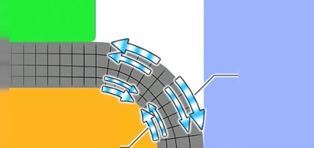
Taking a 90-degree bend as an example, the forces are highly uneven post-bending. Due to opposing forces on the inner and outer sides, the product will spring back when the external force disappears, with the size closely related to the internal radius (R) and bending angle.
- Die Design:
Includes the die’s geometric shape, angles, and fillet radii, all significantly impacting springback. Key aspects include:
Part shape: U-shaped parts have smaller springback angles than V-shaped parts; complex bent parts formed in one go have less springback as the number of bends increases.
Die clearance: Larger clearances in U-shaped bending dies result in greater springback; negative springback can occur when z/2 < t.
- Stamping Conditions:
Include stamping speed and pressure, also affecting springback:
Bending speed: The speed of processing can affect the material’s temperature and stress state during bending, thus impacting springback.
Lubrication conditions: The type and amount of lubricant used during bending can reduce friction between the material and the die, affecting springback.
Processing temperature: High-temperature processing can reduce material yield strength, decreasing springback. Cold processing may increase springback.
By understanding and controlling these factors, one can better predict and compensate for springback, optimizing product design and processing. In practice, it’s often necessary to adjust processing parameters and die designs based on specific materials and product requirements to achieve optimal processing results.
3. Calculation of Bending Springback in Stamping Die
The calculation of springback coefficients during bending considers the following:
- Springback Coefficient Formula:
Springback percentage (%) = (δ-ε)/δ × 100%
δ is the maximum deformation, ε is the residual deformation. - Influencing Factors:
Material type, thickness, bending radius, and angle all affect the springback rate. Typically, the springback rate is inversely proportional to the bending radius and directly proportional to the angle. Thicker materials exhibit higher springback rates. - General Material Springback Rates:
Carbon steel: About 30%
High-speed steel: About 25%
Stainless steel: About 10% - Calculation Example:
For a 2mm thick die steel plate requiring a 90° bend with an internal radius R=4mm:
Predicted maximum deformation δ = 2mmθ = 2mm90°/180° = 1mm
Predicted residual deformation ε = 10% of δ, i.e., 0.1mm
Springback rate = (δ-ε)/δ = (1mm-0.1mm)/1mm = 90%
These are estimates, and actual operations require trial production for verification. Using trial data to correct calculation parameters can more accurately assess springback rates under different conditions.
4. Stamping Die Material HV Chart
Material hardness is a crucial factor in bending spring back during die-making. Hardness represents the bonding strength between material molecules. Higher hardness means greater molecular binding force and poorer elasticity, resulting in lower spring back rates. If you are not very familiar with the hardness of common stamping materials, refer to the following comparison table to understand:
| Material | Grade | Hardness Category | Hardness Value (HV) |
|---|---|---|---|
| Phosphor Bronze | C5191 | R-H | HV190~210 |
| Phosphor Bronze | C5191 | R-EH | HV210~230 |
| Phosphor Bronze | C5191 | R-SH | HV230~250 |
| Phosphor Bronze | C5210 | R-H/2 | HV150~180 |
| Phosphor Bronze | C5210 | R-3/4H | HV160~190 |
| Phosphor Bronze | C5210 | R-H | HV190~210 |
| Phosphor Bronze | C5210 | R-EH | HV210~230 |
| Phosphor Bronze | C5210 | R-SH | HV230~250 |
| Nickel Silver | C7521 | R-OH | HV80~110 |
| Nickel Silver | C7521 | R-1/2H | HV140~180 |
| Nickel Silver | C7521 | R-H | HV170~190 |
| Brass | H62 | R-H/2 | HV100~150 |
| Brass | H62 | R-H | HV140~180 |
| Brass | H65 | R-H/2 | HV100~150 |
| Brass | H65 | R-H | HV140~180 |
| Stainless Steel | SUS304 | BA | HV160~200 |
| Stainless Steel | SUS304 | 2B | HV120~160 |
| Stainless Steel | SUS304 | R-H/2 | HV250~310 |
| Stainless Steel | SUS304 | R-3/4H | HV310~370 |
| Stainless Steel | SUS304 | R-H | HV370~420 |
| Stainless Steel | SUS304 | R-EH | HV420~450 |
| Stainless Steel | SUS304 | R-SH | HV450 and above |
| Stainless Steel | SUS301 | R-H/2 | HV310~370 |
| Stainless Steel | SUS301 | R-3/4H | HV370~420 |
| Stainless Steel | SUS301 | R-H | HV420~450 |
| Stainless Steel | SUS301 | R-EH | HV450~490 |
| Stainless Steel | SUS301 | R-SH | HV490 and above |
| Stainless Steel | SUS430 | M | HV150~200 |
| Beryllium Copper | C17200 | TM04 | HV285~369 |
| Beryllium Copper | C17200 | HMB | HV285~369 |
| Nickel Strip | M | HV80~110 | |
| Nickel Strip | 1/4H | HV110~140 | |
| Nickel Strip | 1/2H | HV140~170 | |
| Nickel Strip | H | HV185~210 | |
| Copper Titanium | H/4 | HV250~300 | |
| Copper Titanium | H/2 | HV270~320 | |
| Copper Titanium | H | HV280~300 | |
| Copper Titanium | EH | HV300~350 |
4. Stamping Die Bending Springback Chart for Different Materials
From the calculation of bending springback coefficients above, we see that besides material type, bending angle and internal radius size significantly influence springback. If you want to determine the relationship between springback size and these factors more accurately, the following calculation formulas and comparison tables are essential. With them, you can more accurately calculate the angle size, reducing the trial mold cycle.
| Material | Thickness (mm) | Elastic Modulus | Part Radius (mm) | Punch Radius (mm) | Part Angle (°) | Punch Angle (°) |
|---|---|---|---|---|---|---|
| Soft Stainless Steel | 0.1 | 0.0044 | 0.5 | 0.489 | 90 | 88.02 |
| Soft Stainless Steel | 0.2 | 0.0044 | 0.5 | 0.495 | 90 | 89.01 |
| Soft Stainless Steel | 0.3 | 0.0044 | 0.5 | 0.496 | 90 | 89.34 |
| Soft Stainless Steel | 0.3 | 0.0044 | 1 | 0.986 | 90 | 88.68 |
| … | … | … | … | … | … | … |
| Hard Stainless Steel | 2.5 | 0.018 | 5 | 4.826 | 90 | 86.76 |
| Phosphor Bronze | 0.1 | 0.015 | 0.5 | 0.465 | 90 | 83.25 |
| … | … | … | … | … | … | … |
| Low Carbon Steel | 1.5 | 0.0032 | 3 | 2.981 | 90 | 89.424 |
| Copper | 0.5 | 0.0019 | 1 | 0.996 | 90 | 89.658 |
| … | … | … | … | … | … | … |
| Soft Aluminum | 1 | 0.0012 | 3 | 1.989 | 90 | 89.676 |
| Hard Aluminum | 1 | 0.0041 | 3 | 2.964 | 90 | 88.893 |
5. How to Solve Bending Springback Issues in Stamping Die Making
Here is an example of how to address bending springback issues in mold making: A machine tool company needs to produce a gear punching die, including a 90° curved bending structure.
- Selecting Die Material: After evaluation, 36 steel with a 0.4% C composition is chosen as the die material.
- Calculating Bending Parameters: Based on a 25% springback rate for 36 steel, the curved bending line length is calculated as 125% of the original straight length.
- Choosing the Internal Diameter: Based on the material hardness and a thickness of 5mm, an internal diameter of 6mm, ratio 1.2, is selected.
- Producing a Trial Piece: The bending groove line is first cut using a CNC machine, then bent with appropriate pressure.
- Testing Results: Significant springback is observed, with the bending angle insufficiently reaching 90°.
- Improving the Trial: Increase the internal diameter to 7mm and double the length of the bending arc for a second bend to achieve a 90° bend.
- Retesting: The bending results are satisfactory, and the curved bending meshes well.
- Establishing Official Processes: Improved parameters such as an internal diameter of 7mm and double the arc length are documented in the official processing procedures.
This example demonstrates how through parameter adjustments and multiple trials, bending springback issues can be effectively resolved, ensuring mold quality.

