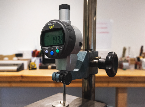
What is Dial Indicator: Advantages, Applications, How To Use & Fix
In the field of mechanical manufacturing, using a dial indicator to center a workpiece along the X and Y axes is a common operation. This ensures that the workpiece is centered in both directions, achieving higher precision and quality. However, in practice, we find that directly using a traditional dial indicator for centering can introduce some errors. The main reason is that the lowest point of a traditional dial indicator is not entirely consistent, causing slight differences in readings at different positions. This can result in the lowest point of the workpiece not aligning perfectly after centering along the X and Y axes, leading to positioning errors that affect subsequent processes or product performance. Today, we will teach you how to use a dial indicator for centering in a machining center.
Advantages of Dial Indicators
Improved Positioning Accuracy: Since its lowest point reading is consistent at any position, centering along the X and Y axes maximizes the overlap of the workpiece’s lowest point. This greatly enhances final positioning accuracy.
Error Reduction: It avoids the accumulation of small errors caused by differences in the lowest points of traditional surfaces. This is particularly crucial in the manufacture of fine parts where high precision determines product quality.
Strong Repeatability: Due to the stable and reliable lowest point reading, positioning errors are minimized, and repeat positioning capability is excellent.
Compatibility with Different Specifications of Workpieces: Unlike traditional indicators, its lowest point does not depend on the surface structure, allowing it to handle workpieces of various specifications and sizes, facilitating line changes in production.
Ease of Automation: The consistency of readings makes parameter settings simpler, and both use and adjustment are more convenient, making it more suitable for automated production lines.
Applications of Dial Indicators
High-precision Positioning in Small Parts Manufacturing: Such as microelectronic components, optical elements, etc., where error control is below the micron level.
Automated Production Lines Requiring Repeat Positioning: Such as automated assembly lines for electronic products or phone components, where higher repeat positioning accuracy is required.
Flexible Production with Multiple Specifications of Workpieces: This indicator structure is independent of the material, allowing different workpieces to be alternately produced on the same equipment.
Mirror and Optical Product Manufacturing: Due to high-precision surface performance requirements, consistent lowest points help improve positioning accuracy and optical performance.
Industrial Robot Joint Positioning: Robot arms that work repetitively require high-precision positioning, and this type of indicator structure can enhance the continuity of robot movements.
Precise Positioning in 3D Printing Fields: For example, metal 3D printing requires ensuring the accuracy of layer stacking.
Methods and Precautions for Using a Dial Indicator for Machining Center Centering
Methods:
- Select an appropriately sized and accurate dial indicator according to the workpiece size.
- Roughly place the workpiece on the surface and use a light to observe and select the starting positions for X and Y axis readings.
- Adjust the machining center’s X and Y axes respectively, setting the dial indicator surface height to zero, and record the current positions of the X and Y axes.
- Analyze the difference between the workpiece center and the zero position based on the readings, and calculate the distance the X and Y axes need to move.
- Input the calculated X and Y axis movement distances to achieve centering and positioning movement, accurately placing the workpiece center on the surface center.
Precautions:
- The surface must be kept flat and clean to avoid dust affecting readings.
- When using an electronic indicator, readings should be taken without power to avoid magnetic field interference.
- Maintain consistent viewing angles to prevent visual errors.
- Readings should be taken to at least two decimal places to improve positioning accuracy.
- Use the geometric center of the workpiece as the judgment standard when verifying the centering effect.
- After centering, conduct a review to eliminate errors caused by system errors and other factors.
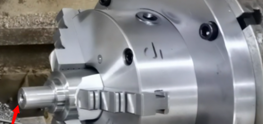
Finding and Adjusting the Minimum Point of the CNC Machining Center Spindle
Finding the minimum point of the CNC machining center spindle is a crucial step to ensure machining accuracy. The accurate positioning of the spindle’s minimum point directly affects the workpiece’s positioning accuracy within the machining center. Generally, the following methods can be used to find and adjust the spindle’s minimum point:
First, turn off the power to the machining center spindle to prevent it from rotating during the operation. Then, use a pointer tool or other sharp tools to start measuring from different directions and heights of the spindle surface. Through multiple contact tests at different positions, the point with the smallest reading can be identified as the lowest point on the spindle surface. Mark this position with a marker for identification.
After locating the minimum point, manual fine-tuning of the spindle position can begin. Turn on the spindle power without rotation, and use the handwheel or micro-adjustment device to roughly align the spindle to the minimum point. Then, take readings at the marked minimum point using an electronic indicator as the reference. Gradually adjust the spindle using the handwheel until the reading deviation is minimized, thus accurately adjusting the spindle to the lowest point. During this process, feedback readings should be taken for every slight adjustment until convergence to zero.
After adjustment, lock the spindle in place to prevent position shifts. Finally, use fixtures or other tools to check the adjustment effect, ensuring that the spindle’s minimum point is correctly positioned, thus guaranteeing high precision in subsequent CNC machining