Why and How to Use Calculated Dimensions in CNC Machining Programming
As CNC machinists, we are often tasked with programming parts where certain features are defined by calculations rather than fixed dimensions. This article will explain some challenges that can arise when using calculated values in CNC machining, provide mechanical drawing dimension calculation examples, and offer best practices for overcoming issues.
Why Use Calculated Sizes Instead of Direct Markings on Mechanical Drawings?
– Determining the size through calculation can take into account various error factors in the processing and use of mechanical parts, making the actual size of the conical hole closer to the design requirements.
– Calculating the size is easier to modify in the later stages. If a fixed size is directly marked, but the design needs to be changed, all drawings need to be modified; while calculating the size only requires adjusting the parameters.
– Adopting the calculation method lays the foundation for possible digital manufacturing in the future. If the control code is directly generated through programming software, it is easier to convert the calculated size into digital values.
– Marking the calculation method instead of a fixed size emphasizes the scientificity, accuracy, and traceability of the product design, which is beneficial to product quality management and problem investigation.
Challenges of Using Calculated Dimensions
There are a few potential difficulties when relying on calculated dimensions rather than explicit sizes:
- Variations in actual machined features: Due to tolerances in stock material dimensions and tool/machine inaccuracy, directly machined features may not perfectly match the calculated target size.
- Inconsistencies between features: Factors like tool wear over time can cause inconsistency if multiple features rely on the same calculation.
- Programming complexity: Expressing calculations precisely in G-code requires translating geometric formulas.
- Troubleshooting errors: If features do not meet design intent, it may be harder to trace the root cause when using calculations.
Examples of Dimension Calculations in CNC Machining
To illustrate challenges, consider these examples:
– Example 1) Machining a cylinder to have two ends at the calculated diameter of 2 inches. Issues could arise if the actual cut diameters are slightly differently sized.
– Example 2) Milling symmetrical pockets in a square part where the pocket widths are each calculated based on the block length. Wear on different cutters could result in non-identical pockets.
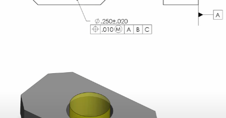
– Example 3): a specific calculation for the inner diameter of the tapered hole.
Outer diameter D1 = 100mm
Length L = 70mm
Inner angle α = 10°
Calculate the inner diameter:
tanα = (opposite side / adjacent side)
tan10° = Ο / 70
Ο = 70*tan10° = 70.174 = 12.18mm
Inner diameter D2 = D1 – Ο = 100 – 12.18 = 87.82mm (rounded to 87.8mm)
The following G code can be used to achieve the calculation in Example 3:
N1 G92 X0 Y0 Z0; Define the coordinate system origin
N2 T1 M06; Select the first tool group
N3 G00 X100 Y0 Z50; Move to the starting point of the outer circle
N4 G01 Z-10 F300; Enter cutting
N5 G03 X0 J-100 F200; Cut the outer circle arc
N6 G00 Z50; Calculate the inner diameter
N7 D1=100
N8 D2=70
N9 A=10 (Angle is 10°)
N10 R=D2*TAN(A*(3.14/180))
N11 D3=D1-R (Inner diameter = outer circle diameter – calculated depth)
N12 G00 XD3 Y0 Z50; Move to the starting point of the inner circle
N13 G01 Z-10; Enter cutting
N14 G03 X0 J-D3 F150; Cut the inner circle arc
N15 G00 Z50
N16 M30; End Programming
By calculating the inner diameter based on the specific size, you can achieve the drilling requirement. The key is to correctly use the trigonometric function to calculate the drilling depth, and then obtain the inner diameter size.
| Example | Machining Goal | Calculation | Potential Difficulty |
|---|---|---|---|
| 1 | Machining a cylinder to 2 inches diameter | Diameter = 2 inches |
|
| 2 | Milling symmetrical pockets based on block length | Pocket width = Block length / 2 |
|
| 3 | Calculating inner diameter | Inner diameter D2 = D1 – Ο = 100 – 12.18 = 87.82mm (rounded to 87.8mm) |
|
Calculated Programming Techniques
To address these challenges, machining engineers should:
- Include tolerances around calculated values and consider adjustment loops if needed.
- Monitor for tool wear that could introduce inconsistencies between like features.
- Write G-code rigorously to avoid transcription errors of formulas.
- Be prepared to troubleshoot by working backward from actual measurements to the original calculation inputs.
- Consider adding post-operations that fine-tune the matching of features within a tight tolerance band.
This approach helps maximize the advantages of parametric, feature-driven designs while compensating for real-world machining variability. With care and practice, CNC programs can reliably deliver parts meeting design intent even when dimensions derive from calculation processes.